We’ve been tinkering, experimenting, and possibly bending reality a little…
And somehow ended up with this:
👉 Direct SDR-to-RF FM-ATV modulation
Straight onto frequency. No detours. No magic boxes. Just your SDR doing its thing. High quality, low noise, high linearity. It’s next level.
👉 Wide frequency coverage: ~60 MHz to 6000 MHz
Because choosing bands is overrated anyway. Why not all of them?
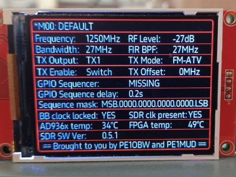
👉 Control via the Digital Baseband screen
Yes, the same screen. No extra knobs, no extra apps — just turn and press to configure, transmit, and question your life choices.
- You will have the option to add a momentary switch to control “TX-ON – TX-OFF”, but it’s not mandatory.
- An option to add a second screen (identical screen, same rotary, and some extra buttons) will become available for dedicated transmitter (SDR) control. Freeing up your Digital Baseband Display to just show those nice PPM’s.
👉 Includes Itch-free SDR™ mode: clinically proven to eliminate delay-induced frustration.*
*(ODJ-Approval-proof)
👉 Some units are in test already
The feedback is incredibly positive. Within a week of asking ‘Who would be interested?’ over 50% of digital baseband’s sold look like they will be receiving the add-on. PI6ZTM and PI6ATV are looking to replace their main ATV transmitters with this system. How cool is this!
Obviously it’s new software V2.0 for your existing Digital Baseband. You will need some additional hardware:
You will specifically need this SDR: https://opensourcesdrlab.com/products/new-7020-ad9363-plutosdr?DIST=RkdOGl8%3D
If you want the version with the amplifier, use this one: https://opensourcesdrlab.com/products/new-7020-ad9363-plutosdr?DIST=RkdOGl8%3D
These are the bare boards with GPIO’s, the Zync 7020 FPGA and the AD9363 “RF agile transceiver”.
You could opt for the AD9361, which does officially support the wider frequency range and bandwidths we’re pushing, but so far we’ve found the Pluto-SDR ‘hack’ (using the AD9363 as if it were an AD9361) to be indistinguishable from the real thing. So we’d say: go for the cheaper option but beware there are no guarantees that future revisions of the silicon will stay compatible.
If you don’t like this risk, go for the AD9361: https://opensourcesdrlab.com/products/opensourcesdrlab-new-plutosky?DIST=RkdOGl8%3D
It is the board including the enclosure. A very nice product and the price.. it’s worth it.
As for choosing the version with the amplifiers: it’s totally up to you. We prefer external amplifiers since they can be replaced more easily if they break. But again, it’s up to you.
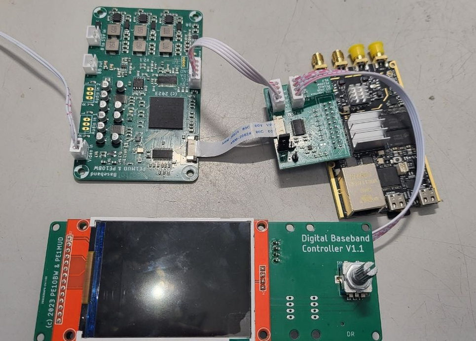
A Brief Description of the Architecture:
The digital baseband produces a 12-bit baseband signal running at a sample rate of 49.152 MHz adding up to a total of close to 600 megabit/s. This data is not only sent to the onboard 12-bit DAC for the analog output signal but using the optional FPC from the digital baseband, originally designed for 64 kbit/s I2S, we are able to also transfer this data to the SDR using a DDR core. In the SDR, a FIFO is used to align clocks, and some I2C is added for control of the transmitter functionality. The clock of the digital baseband locks to the SDR clock, to obtain a fully synchronous setup.
The SDR feeds the data to a Direct Digital Synthesizer, producing I/Q signals that use zero-IF modulation to generate FM-ATV on the desired frequency. Optional FIR filtering can be enabled to limit the output bandwidth. An analog filter following the I/Q modulator eliminates spurious signals.
A wide-range attenuator (-89 to 0 dB) allows the desired output level to be set. Since the SDR is a wideband design using 3 GHz baluns, the output levels are not consistent across the full frequency range, but this is where your skills as a licensed radio amateur come in handy.
In the release version, we may choose to limit the output attenuator to a maximum of -10 dB, as beyond this level the RF performance of the AD9363 deteriorates.
One part we have not mentioned yet is the addition of a 16-bit sequencer, which will provide options to switch transfer relays, amplifiers, and other peripherals according to your requirements.
#FMATV #SDR #DigitalBaseband #Awesome

We will post a technical description of the inner workings of the Digital Baseband on this page.
The Digital Baseband is realized in a Field Programmable Gate Array, or FPGA. An overview of the hierarchy and components comprising the FPGA will be included. This Digital Baseband incorporates a NICAM encoder which is based on the NICAM encoder Werner developed back in 1999, with the help of Willem PE1PCF. That encoder used a Digital Signal Processor (DSP) in conjunction with an FPGA, and required external filtering to shape the NICAM modulate.
Since the FPGA used in the Digital Baseband is roughly 200 times more powerfull than the FPGA used in the original NICAM encoder, the DSP and external filters are no longer needed as the FPGA can easily perform these tasks.
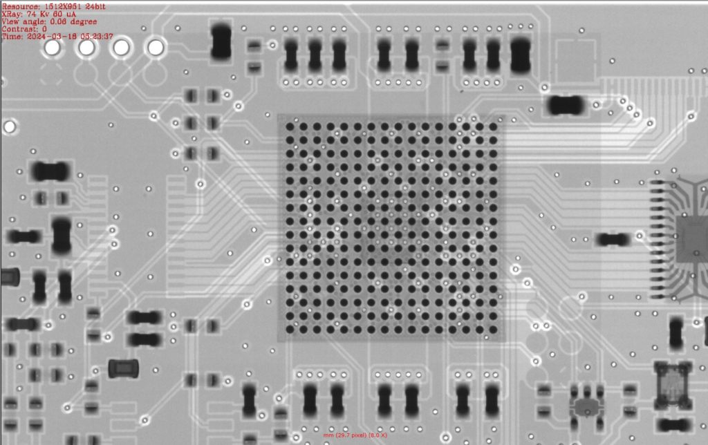
One of the production steps is that the BGA’s are inspected using X-Ray technology. Here is a capture of such an inspection.
The digital baseband offers pre-emphasis and steep 5MHz filtering (without any C/L delay issues), NICAM, 4 FM channels, text overlay (for call and so on), morse code generator (for call and so on) and some test cards and a bessel null function to align your FM transmitter. As per version 1.4, the first 8 characters of the morse code ‘MSG’ are transmitted in the additional databits inside the NICAM data. This allows nicam decoders to display your station ID (CALL). All is controlled by an ESP32 with a 320×240 display. See the manual section for more details.
November 2024 update: new boards are incoming! You can contact us if you want to buy one.
If your digital baseband is broken, kaputt, stuk or just doesn’t work, please contact us! We will do our best to solve the problem for a friendly price.
October 2025 updates:
All boards are sold out.- A new firmware version has been released (v1.4)! See the announcement in the download section.
- A document “Reading the station ID from NICAM using the MSP34x5G” has been added to the software updates section
May 2026 Update!
We are going to make a limited batch of new Digital Basebands (same revision as before, no changes). Our addition of an SDR has driven requests to a level we can’t ignore anymore.
So, if you’re interested and want to buy one, post something below….
Cheers!
Team FM-ATV
Interesting Project:
Please advise Pricing and shipping parts etc
To AU maybe some interest with a few Blokes Downunder
Thanks
Rob
Hi Rob,
Thanks for dropping a note here. I’ll just reply here so everyone can read about the status.
The Digital Baseband kit is fully built and tested, only the board connectors (supplied incl. matching cables) need soldering. We’ve done this so you could use different connectors/wiring if you so desire. Such a kit includes the Digital Baseband board itself and the controller board with display.
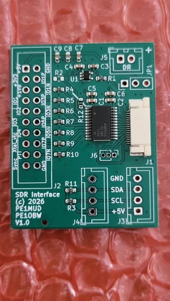
The SDR interface board comes fully built and tested and connects to the Digital Baseband using an FFC (Flat Flexible Cable). It plugs straight into the SDR’s GPIO connector. The SDR needs to run our image (all software will be available for free).
As for shipping….
We never intended to sell these kits abroad, we’ve only sold them to friends local to our ATV repeaters. Even ATV repeaters here use them 🙂
Bottomline: we will have to do some research on international shipping and on producing larger numbers. This may start to look like work, something we wanted to stay away from 🙂
As for pricing, the price varies a bit per batch, depending mostly on components availability and batch size. For the Digital Baseband the price range so far has been from 275 to 325 Euro. The SDR interface board sells for 25 Euro.
I’ll send you an email too, so we can discuss further details.
Out of curiosity: are you using NICAM in AU? Do you have bandwidth restrictions on FM-ATV?
Cheers,
David
How do we contact you without publishing our details?
Your email address is visible to us…. but we’d like you to tell us what it is that you want to discuss first.
Sorry, but we’re getting lots of spam/phishing/bs messages.
Hallo david,
Mooi project👌
Is er nog een baseband en interface beschikbaar?
Groet Eric (PA4ERC)
Hi Eric,
Dankjewel.
Zeker wel, ik zal je een email sturen!
Groet,
David
Ben geinteresseerd in de nieuwe digitale baseband. Ik heb al zon sdr board van zynq. Wat heb ik allemaal nog meer nodig?
Groeten Rusty PA0X Aalten.
Dat staat hierboven helemaal uitgelegd.
Goedenavond David, hier ook interesse in de SDR interface.
Je hebt al een digital baseband?
Ik wil graag zon digitale baseband bestellen? Hoe gaat dit verders qua bestellen?
Ik stuur je wel een emailtje 🙂
Kennelijk heb je geen interesse? Ik zag nog geen reactie in de email.
Mooi project,
ik zou graag een baseband en interface willen bestellen (PA4ERC)
Dank!
Jep, ik had je eerdere berichtje gemist, excuses (ik zit er niet bovenop, zogezegd).
Mail volgt!
-David en Werner
Ik zou graag 1 komplete module willen bestellen.
S de Vries PC9X
Hi Sven, zie je email!
Groet,
FM-ATV team
Hi,
Is er nog een complete module beschikbaar?
Bert, PA0XHF
Hi Bert,
Ja, ik zal je mailen dit weekend. Sorry voor de delay!
Groet,
David